Lab 1
Part 1: Communicating between the Uno and IDE
For this part of the lab, we simply loaded up the Blink example code to the Arduino, and watched for the blinking light on the built-in LED.
Part 2: Modify the Blink Sketch
For this part, we modified the Blink example by adding a new variable for another pin, and replacing all instances of pin 13 in the code with our new pin variable. We also attached an LED to pin 0, in series with a 330 ohm resistor. The result was the LED we had attached to pin 0 would blink every second.
        int pinnumber = 0;
        // the setup function runs once when you press reset or power the board
        void setup() {
            // initialize digital pin LED_BUILTIN as an output.
            pinMode(pinnumber, OUTPUT);
        }
        // the loop function runs over and over again forever
        void loop() {
            digitalWrite(pinnumber, HIGH);   // turn the LED on (HIGH is the voltage level)
            delay(1000);                       // wait for a second
            digitalWrite(pinnumber, LOW);    // turn the LED off by making the voltage LOW
            delay(1000);                       // wait for a second
        }
Part 3: The Serial Monitor and the Analog Pins
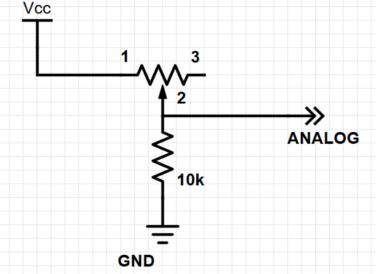
For this part of the lab, we set up a simple voltage divider circuit using the potentiometer as the output resistance and a 10k Ohm resistor as the series resistance. To set up the serial monitor, we used the call Serial.begin(9600) in the arduino setup, which begins transmitting serial data at a rate of 9600 bits/second. Then, we used an analog read on the pin measuring voltage across the potentiometer, in range 0 to 5V as an integer from 0 to 1023. After reading this integer, we converted it to a voltage, multiplying by float 5.0/1023.0 and displaying the result to the serial monitor. We then observed a changing voltage as we turned the potentiometer dial for each analog pin pinname (shown below), as expected.
        int pinname = A5;
        void setup() {
            // put your setup code here, to run once:
            Serial.begin(9600);
        }
        void loop() {
            // put your main code here, to run repeatedly:
            float val = analogRead(pinname);
            val = val * (5.0/1023.0)
            Serial.println(val);
        }
Part 4: Analog Output
For this part of the lab, we re-used the potentiometer setup, and connected an LED to pin 11 in series with a 330 ohm resistor. By calling analogWrite with the value read in from analogRead after rescaling it, we were able to dim the LED using the potentiometer.
      int pinname = A5;
      void setup() {
          // put your setup code here, to run once:
          Serial.begin(9600);
          pinMode(11,OUTPUT);
      }
      void loop() {
          // put your main code here, to run repeatedly:
          float val = analogRead(pinname);
          val = val*(255.0/1023.0);
          analogWrite(11,val);
          Serial.println(val);
      }
Part 5: Parallax Servos
In this part, we again re-used the potentiometer-LED setup, replacing the LED with the servo so we could change the speed and direction of rotation using the potentiometer. To setup the servo in arduino, we initialized a global servo object thisServo and attached the digital output pin servopin so it could begin accepting values 0 to 180 from the board. As before, we also set up the pin being used as output and started the serial monitor so we could observe the values being sent to the servo. In the loop, we “fixed” the analog output from the voltage divider circuit, multiplying the integer 0 to 1023 value by 180.0/1023.0 since the servo accepts input from 0 to 180. As we changed the resistance of the potentiometer, changing the value being output to the servo and serial monitor from 0 to 180, we observed the servo spinning quickly at a value of 0, slowing to a stop at 90, and speeding up in the opposite direction to 180, as expected from the lab description.
      #include <Servo.h>
      int servopin = 11;
      int pinname = A0;
      Servo thisServo;
      void setup() {
          Serial.begin(9600);
          pinMode(servopin,OUTPUT);
          thisServo.attach(servopin);
      }
      void loop() {
          float val = analogRead(pinname);
          val = val*(180.0/1023.0);
          Serial.println(val);
          thisServo.write(val);
      }
Part 6: Assemble and Run Your Robot
Hardware:
Materials used were the: arduino, chassis parts, wheels, ball bearing, servos, battery, zip ties, holders
The chassis parts we used were the body, the servo mounts, and the ball bearing mount. The servo mounts were attached to the servo and the body of the robot using screws. The ball bearing was also fastened to the other end of the body with a screw. We attached both the arduino and battery on top using screws and zipties to keep it steady.
Software:
We set up the code by first attaching the servos on pin 5, representing the left wheel, and pin 3, representing the right wheel. First, we turned both wheels on, making the robot go straight, using the write(on) function with on set to 30 instead of full speed to prevent the robot from going too quickly. We realized the left wheel started off counterclockwise so we fixed this by writing to the left wheel 180 subtracted by on. After going straight for about 1.2 s, we then implemented the turn in the next cycle. The turn was done by turning the left wheel off and keeping the right wheel on for also about 1.2 s.
      #include <Servo.h>

      Servo left ;
      Servo right ;
      int t = 0 ;
      int on = 30 ;
      int off = 90 ;

      // the setup function runs once when you press reset or power the board
      void setup() {
          left.attach(5) ;
          right.attach(3) ;
      }

      // the loop function runs over and over again forever
      void loop() {
          //move left wheel if t=0, else right
          if (t == 0) {
              left.write(180-on);
              right.write(on);
              t = 1;
          } else {
              left.write(off);
              right.write(on);
              t = 0;
          }
          delay(1200);
      }
Task Division
- Lauren and Peter: Part 1 through Part 5 (we were learning how to use Arduinos)
- Christine and Mark: Part 1 through Part 6